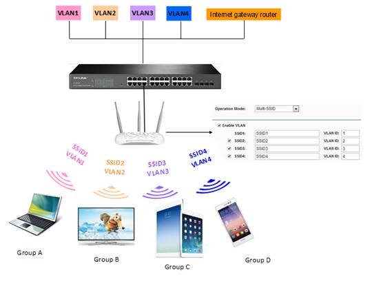
Figure 1. VLAN topology
II. Configuration
It’s quite easy to configure this VLAN function for different SSIDs. Below shows you what to do:
1. Connect your TP-Link AP to your computer with a cable. Manually configure computer’s IP address to be in the same subnet with AP. Then log into Management Page.
2. Go to Wireless->Wireless settings;
Choose Multi-SSID as Operation Mode; Check “Enable VLAN”; then assign VLAN ID for each SSID. When all finished, click Save.
Figure 2. Multi-SSID Settings
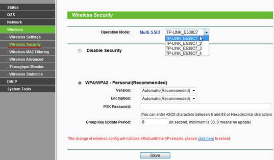
3. Till now, the wireless is still unsecured. Go to Wireless Security and secure each network. Different security type could be used for different SSID.
Figure 3. Multi-SSID Security
III. VLAN Configuration on Switch
As is illustrated in the topology, there are 4 VLAN groups configured on the switch and both the AP and the Internet gateway router are connected to the ports of the switch, here we suppose AP is connected to Port 1 and the Internet gateway router is connected to Port 2,vlan1 includes port 1,2,3,4; VLAN 2 includes port 1,2,5,6; VLAN 3 includes port 1,2,7,8; VLAN 4 includes port 1,2,9,10.After the configuration on the switch, we aim at that VLAN groups are isolated with each other while all of the VLAN groups can get access to the internet.
On the switch, please select “802.1Q VLAN” and follow the steps below,
1.Create VLAN 2, VLAN 3 and VLAN 4 corresponding to the Multi-SSID VLAN ID of the AP.
Chart 1. Create VLAN groups
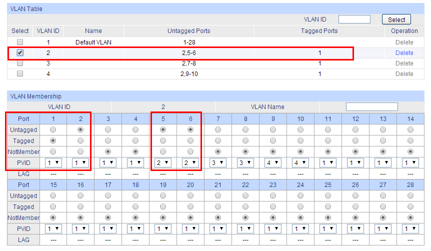
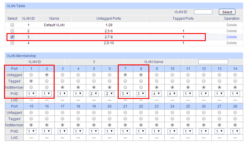
2.Configure the parameters for each VLAN,
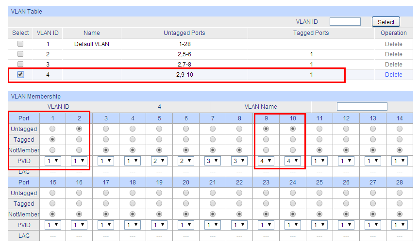
Configure Port type. Port 1 must be configured as “ tagged” while Port 2 must be configured as “untagged”. For other ports, leave them as untagged ports.
Add member ports. Both Port 1 and Port 2 must be the member ports of VLAN 1, VLAN 2, VLAN 3 and VLAN 4.
Set PVID.The PVID of Port 1 and Port 2 should be“1” and PVID of the other ports should be consistent with the corresponding VLAN ID.
(for example, port 3 belongs to VLAN 1,then its PVID should be 1;port 10 belongs VLAN 4,then its PVID should be 4).
Chart 2.Configuration On VLAN 2
Chart 3.Configuration On VLAN 3
Chart 4.Configuration On VLAN 4
3.After click on “Save config”, you will get the following VLAN table,
So far, Multi-SSID (VLAN groups) of AP could cooperate with switch’s 802.1Q VLAN groups, only group is isolated by VLAN ID while all of the groups have internet access.
Note:When Configuring 3 Serial TP-Link switch(e.g TL-SG3424) and 5 serial switch(e.g TL-SL5428E),there are three kinds of port types:Access,Trunk and General;In that case,you must set port 1(the port that connected to AP) as “General tagged” only for VLAN2,VLAN3,VLAN4(excluding VLAN1). Set port 2(the port to the internet gateway router) as “General untagged”.Other ports should be set as “General untagged”, also all group ports should be included in VLAN1.
.jpg)



.jpg)


